ad1

Wednesday, December 30, 2015

connectRules.il

The connectRules.il file contains the built-in connect rules that are displayed in the Select Connect Rules form.


ADE searches for the connectRules.il file in the following locations. If multiple connectRules.il files are located, their contents are concatenated and displayed in the Select Connect Rules form.

  • All libraries defined in the cds.lib file
  • Current work directory
  • $HOME directory
  • $CDS_HIER/share/cdssetup/ams/

Path specified by the connectRulesPath variable in the .cdsenv file. All Cadence-supplied connect rules are stored in the connectRules.il file in the
tools/affirma_ams/etc/connect_lib/connectLib
directory in your Cadence Incisive Unified Simulator (IUS) installation directory.

You can use the genConnRulesFile command to automatically compile your user-defined connect rules into a custom connectRules.il file.


Sunday, December 27, 2015

OCEAN Script Template

;; initialization
(setq designName "./spectre/schematic/netlist/netlist")
(setq resultPath "./spectre/result")
(setq modelName "model.lib")
(setq saveFile "save.scs")
(setq corners list("ss" "ff" "tt"))


;; run script
ocnWaveformTool('wavescan )
simulator('spectre )
design(designName)
analysis(
        'tran
        ?stop "8.814u"
        ?errpreset "conservative"
)
desVar(  "VRP" 1.2 )
desVar(  "VRN" 0 )
desVar(  "AVDD12" 1.2 )
envOption(
'userCmdLineOption  "+aps +parasitics +mt=20"
)
option(
        'nthreads  "30"
        'multithread  "on"
        'temp  "85"
)
saveOption('nestlvl "1")
saveOption('save "selected")

foreach(corner corners
        resultsDir(sprintf(nil "%s/%s" resultPath corner))
        modelFile(
                list(modelName sprintf(nil "%s" corner))
                list(modelName sprintf(nil "res_%s" corner))
                list(modelName sprintf(nil "mom_%s" corner))
                list(saveFile)
        )
        paramAnalysis(
                "temp"
                ?values '(-40 -20 0 55 85 125)
        )
        paramRun()
)

winID=newWindow()
clearAll()
graphicsOff()
foreach(
        corner corners
        openResults(sprintf(nil "%s/%s" resultPath corner))
        selectResults('tran)
        (setq V VT("OUT"))
        plot(V)
)
graphicsOn()


Saturday, December 26, 2015

Waveform & Waveform Family

Use drIsWaveform famIsFamily

(defun fcnName (wave_x @rest wl)
        (let (a b c)
                (cond
                        ((drIsWaveform wave_x)
                                blah blah
                                blah blah
                        ) ; is waveform
                        ((famIsFamily wave_x)
                                (apply 'famMap (constar 'fcnName wave_x wl))
                        ) ; is family
                        (t
                                (error "can't handle %L\n" wave_x)
                        ) ; not a waveform and not a family of waveform
                ) ; cond
        ) ; let
) ; defun


SKILL Internal system variable

autoReload
debugMode
errsetTrace
fullPrecision
integermode
mergemode
printinfix
writeProtect
stacktraceDump
stacktrace
sourceTracing
traceArgs

status & sstatus

status(s_name):
Returns the value of the internal system variable named (s_name). This is an nlambda function.
e.g.


The status function gets a switch. The sstatus function sets a switch.
sstatus(debugMode t)


Friday, December 25, 2015

.oceanrc file

$   ocean
This command loads and reads your .cdsinit file first and then loads and reads the .oceanrc file. You can place OCEAN commands in your .oceanrc file, which is similar to the .cdsinit file.

Draw Waveform From Corner Simulation Result

winID=newWindow()
corners = list("ss" "ff" "tt")
resultPath="./opamp_stb_tb/spectre/PVT"

clearAll()

; Note: 
; graphicsOff()/graphicsOn() helps eliminates the redraw for each plot.
; When graphicsOn() is called, the completed plot appears.
graphicsOff()
foreach
        var  
        corners
        openResults(sprintf(nil "%s/%s" resultPath var))
        selectResults('stb_margin)
        plot(getData("phaseMargin"))
)
graphicsOn()

_adeCreateROF

_adeCreateROF("~")

Corner Simulation Using OCEAN

designName="blahblah/spectre/schematic/netlist/netlist"
resultPath="blahblah/spectre/PVT"
modelFileName="blahblah/model.lib"

ocnWaveformTool('wavescan )
simulator('spectre )
design(designName)
analysis(
        'stb
        ?start "1"
        ?stop "1T"
        ?dec "100"
        ?probe "/V0"
)
desVar("AVDD15" 1.5)
foreach(corner '("ss" "ff" "tt")
        resultsDir(sprintf(nil "%s/%s" resultPath corner))
        modelFile(
                list(modelFileName sprintf(nil "%s" corner))
                list(modelFileName sprintf(nil "bjt_%s" corner))
                list(modelFileName sprintf(nil "dio_%s" corner))
                list(modelFileName sprintf(nil "res_%s" corner))
        )      
        paramAnalysis(
                "temp"
                ?values '(-45 -20 60 85 125)
                paramAnalysis(
                        "AVDD15"
                        ?values '(1.35 1.5 1.65)
                )
        )
        paramRun()
)

Automatic fold in Vim

set foldmethod=indent

Generate Netlist Using SKILL

simulator('spectre)
design("libName" "cellName" "schematic")
createNetlist()

Fold command in Vim

All folding commands start with "z" -- "z" looks like a folded piece of paper.

zf

Thursday, December 24, 2015

input.scs & netlist

In netlist directory, there are two files called input.scs and netlist respectively, input.scs is used by runSimulation, while the netlist file can be used in ocean script in design command
ocnWaveformTool( 'wavescan )
simulator( 'spectre )
design("xxxxxxx/spectre/schematic/netlist/netlist")
resultsDir("../prj/pll_xxxxx/spectre/schematic" )

Visual Select & Press :

Indent In Normal Mode -- Vim

use > command

Copy To Clipboard in Vim

normal mode:
"+y

ex command:
:%y +

"paMaster" Directory in simulation result directory

This directory is used from Parameter Analysis purpose. It contains an runObjFile file:
HEADER
"PSFversion" "1.00"
"Run Generator" "drlRun rev. 1.0"
"Run Time Stamp" "Dec 24 11:46:49 2015"
"date" "Dec 24 11:46:49 2015"
"simulator" "spectre"
"netlistDir" "../netlist"
"tranSST2Data" "TRUE"
TYPE
"runObject" STRUCT(
"logName" ARRAY( * ) STRING *
"parent" STRING *
"sweepVariable" ARRAY( * ) STRING *
) PROP( "key" "runObject" )
VALUE
"Root" "runObject" (
("")
""
("temp")
)
"temp=-40/psf" "runObject" (
(
"../temp=-40/psf/logFile"
"../temp=-40/psf/artistLogFile"
)
"Root"
()
) PROP(
"netlistDir" "../netlist"
"dataDir" "../temp=-40"
 "temp" -40
)
"temp=60/psf" "runObject" (
(
"../temp=60/psf/logFile"
"../temp=60/psf/artistLogFile"
)
"Root"
()
) PROP(
"netlistDir" "../netlist"
"dataDir" "../temp=60"
 "temp" 60
)
"temp=125/psf" "runObject" (
(
"../temp=125/psf/logFile"
"../temp=125/psf/artistLogFile"
)
"Root"
()
) PROP(
"netlistDir" "../netlist"
"dataDir" "../temp=125"
 "temp" 125
)

Wednesday, December 23, 2015

Use SpectreMDL to run PVT simulation


use command
spectremdl -batch batch.mdl -design design.scs
where the design file is something like:
simulator lang=spectre
global 0
parameters AVDD12=1.2 f_clk=10M
include "model.scs" section=tt
tran_x11 tran stop=300n errpreset=liberal write="spectre.ic" \
    writefinal="spectre.fc" annotate=status maxiters=5
alter_ss altergroup {
include "model.scs" section=ss
}
alter_ff altergroup {
include "model.scs" section=ff
}
alter_sf altergroup {
include "model.scs" section=sf
}
alter_fs altergroup {
include "model.scs" section=fs
}
alter_temp_low alter param=temp value=-45
and the batch file:
alias measurement tran_duty_cycle {
export real dc
run tran_x11
dc=dutycycle(V(OUT))
}
run tran_duty_cycle
analysis item,myAgs[]={alter_ss,alter_ff,alter_sf,alter_fs}
foreach temp from {-45, 45, 125} {
foreach AVDD12 from {1.08, 1.2, 1.32} {
foreach item from myAgs onerror='continue {
// change process corner
run item
run tran_duty_cycle
}
}
}
//run alter_ss
//run alter_temp_low
//run tran_duty_cycle as tran_duty_cycle_2


*Error* Could not select results from xxxx

Put runObjFile into your psf directory will solve this issue.

A sample runObjFile is like
"Run Time Stamp" "Dec 22 21:03:14 2015"
"simulator" "spectre"
"date" "Dec 22 21:03:14 2015"
"tranSST2Data" "TRUE"
"netlistDir" "../netlist"
TYPE
"runObject" STRUCT(
"logName" ARRAY( * ) STRING *
"parent" STRING *
"sweepVariable" ARRAY( * ) STRING *
) PROP( "key" "runObject" )
VALUE
"Run1" "runObject" (
(
"logFile"
"artistLogFile"
)
""
()
)
END

Tuesday, December 22, 2015

Wavescan Mode

Wavescan has two modes:

  • SKILL mode
  • SpectreMDL mode

To use SpectreMDL mode:
wavesan -expr MDL


Saturday, December 19, 2015

BASH History Commands

!$    last argument of previous command (recall $ means last in regular expression)
!!:1  first argument of previous command
!!:2  second argument of previous command

Friday, December 18, 2015

Convert ^M Linebreak to Linux Linebreak Using Vim

%s/<C-v><C-m>//

Recording In Vim

To record typed characters into register:
        q{0-9a-zA-Z"}
(uppercase to append).

To stop recording:
        q

To execute register content:
        @{0-9a-z".=*}
Note that register '%' (name of the current file) and '#' (name of the alternate file) cannot be used.

For "@=" you are prompted to enter an expression.  The result of the expression is then executed.


[EBOOKS] Python For Finance

Python For Finance

IPython Kernel Status

[EBOOK] Troubleshooting Analog Circuits -- By Bob Pease

Click the link below to view the document.
Troubleshooting Analog Circuits

Thursday, December 17, 2015

Circumvent "cdsinit" Calling -- use "nocdsinit" and "restore" options

You could revert to "icfb -nocdsinit -restore myInit" and then have myInit contain:

load(".cdsinit") ; get the path right
envSetVal("asimenv.startup" "simulator" 'string "spectre")

Set ADE Default Simulator

envSetVal("asimenv.startup" "simulator" 'string  "spectre")
or
envSetVal("asimenv.startup" "simulator" 'string  "ams")

Current Direction Of Spectre Simulation Result

into source or component:  positive
out of source or component: negative 

Tuesday, December 15, 2015

SAR Logic For Pseudo-Differential Sampling SAR ADC (Using Verilog-HDL)

`timescale        1ns/10ps
module sar_pseudo_differential_switch_v (adc_output,reset, sample_e, sample, dac_input, dac_input_b,state,pd,clk,comp_out);
input         pd;
input        clk;
input        comp_out;
output        [9:0]        adc_output;
output                reset;
output                sample_e;
output                sample;
output        [9:0]        dac_input;
output        [9:0]        dac_input_b;
output                state;
reg        [9:0]        mask;
reg        [9:0]        adc_temp;
reg                reset;
reg                sample_e;
reg                sample;
reg        [9:0]        adc_output;
//        reg        [9:0]        dac_input;
//        reg        [9:0]        dac_input_b;
reg        [2:0]        state;


// state assignment
parameter sPD=0,  sRESET=1, sSAMPLE=2, sCONV1=3, sCONV2=4;

always @(posedge clk) begin
if (pd)
begin        
state <= sPD;
reset <= 0;
sample_e <= 0;
sample <= 0;
mask <= 10'b0000000000;
adc_temp <= 10'b0000000000;
adc_output <= 10'b0000000000;
end
else
case (state)
sPD:         
begin
state <= sRESET;// next clock edge will start
// reseting capacitor array
end
sRESET:        
begin
state <= sSAMPLE;        // next clock edge will trigger
// sample process
reset <= 1;
sample_e <= 0;
sample <= 0;
adc_temp <= 0;
mask <= 10'b0000000000;
end
sSAMPLE:
begin
state <= sCONV1;        // next clock edge will trigger
// MSB conversion
reset <= 0;
sample_e <= 1;
sample <= 1;
#900;
sample_e <= 0;
end
sCONV1:                                        // begin conversion
begin
state <= sCONV2;        // next clock edge will trigger
// MSB-1 conversion
sample_e <= 0;
sample <= 0;
mask <= 10'b1000000000;
end
sCONV2:
begin
if (comp_out) adc_temp <= adc_temp|mask;
mask <= mask>>1;                                                        // sample process
if (mask[0]) begin
state <= sRESET;        // next clock edge will trigger
// reset process
adc_output <= adc_temp;
end
end        
endcase                                 
end // always

assign dac_input = adc_temp | mask;
//assign dac_input_b = ~dac_input & ~pd & state!=sCONV1 & state!=sSAMPLE & state!=sRESET;
assign dac_input_b = ~dac_input & {10{state==sCONV2}} | {10{reset}}  ;

endmodule

Concatenate {} -- Verilog-HDL

Verilog-HDL power supply

supply0
supply1

AMS Connect Rule File Example

`include "disciplines.vams"
`include "userDisciplines.vams"

`define CONNRULES_18V_FULL_FAST
 `define CONNRULES_18V_FULL
 `define CONNRULES_18V_MID
 `define CONNRULES_18V_BASIC
 `define CONNRULES_FULL_FAST
 `define CONNRULES_FULL
 `define CONNRULES_MID
 `define CONNRULES_BASIC
 `define Vsup  1.8
 `define Vthi  1.2
 `define Vtlo  0.6
 `define Vlow  0
 `define Tr    0.2n
 `define Rlo   200
 `define Rhi   200
 `define Rx    40
 `define Rz    10M
 `define Vdelta      `Vsup/64
 `define Vdelta_tol  `Vdelta/4
 `define Tr_delta    `Tr/20

connectrules ConnRules_1V_full_fast;
  connect L2E_2
      #( .vsup(1), .vlo(0), .tr(0.2n), .tf(0.2n), .rlo(200), .rhi(200), .rx(40), .rz(10M));
  connect E2L_2
      #( .vsup(1), .vthi(0.8), .vtlo(0.2), .tr(0.2n));
  connect Bidir_2
      #( .vsup(1), .vthi(0.8), .vtlo(0.2), .vlo(0), .tr(0.2n), .tf(0.2n), .rlo(200), .rhi(200), .rx(40), .rz(10M));
  connect E2R
      #( .vdelta(`Vsup/64), .vtol(`Vdelta/4), .ttol(`Tr/20));
  connect R2E_2
      #( .vsup(1.8), .vdelta(`Vsup/64), .tr(`Tr/20), .tf(`Tr/20), .rout(200));
  connect ER_bidir
      #( .vdelta(`Vsup/64), .vtol(`Vdelta/4), .ttol(`Tr/20), .tr(`Tr/20), .tf(`Tr/20), .rout(200), .rz(10M));
  connect L2E_2_CPF
      #( .vsup(1.8), .vlo(0), .tr(0.2n), .tf(0.2n), .rlo(200), .rhi(200), .rx(40), .rz(10M));
  connect Bidir_2_CPF
      #( .vsup(1.8), .vthi(1.2), .vtlo(0.6), .tr(0.2n), .tf(0.2n), .rlo(200), .rhi(200), .rx(40), .rz(10M));
endconnectrules

Sunday, December 13, 2015

Save Power Of A Source (Spectre)

save V0:pwr

power=-getData("V0:pwr" ?result 'tran)

energy=-iinteg(getData("V0:pwr" ?result 'tran))

value(energy 9e-06)


Energy Stored In A Cap & Energy Required To Charge Up A Cap


Half of the energy drawn from the source is dissipated by the resistor, no mater how small the resistor is

Saturday, December 12, 2015

Enable C-bit Operations

In C action language chart, when Enable C-bit Operations option is checked, 2^11 = 9, whereas when this options is unchecked, the result will be 2^11=2048.

Action Language Of Charts

There are two action languages for a chart:

  • C
  • Matlab

Use Register in VI ex mode

:%y *  yank all and put it to * register
:4d x   delete line 4 and put to x register


"X Selection" and VI Register

There are three documented X selections:
  • PRIMARY (which is expected to represent the current visual selection); 
  • SECONDARY (which is ill-defined);
  • CLIPBOARD (which is expected to be used for cut, copy and paste operations).
Of these three, Vim uses
  • PRIMARY when reading and writing the "* register
  • CLIPBOARD when reading and writing the "+ register.  
  • Vim does not access the SECONDARY selection.

Add Shortcut To "Unzoom" Command

Inside your .cdsinit file, add:
hiSetBindKeys("wavescan" list(
  list("None<Key>u" "graph.zoom.unzoom")
))


Wavescan Bindkeys

the .il file is in
./tools/dfII/samples/local/
and named wavescanBindKeys.il

Show Currently Used Bind Keys

Friday, December 11, 2015

Register in Vim

Numbered Register 0 - 9
Vim fills numbered registers with text from yank and delete commands.

  • reg 0 contains the text from the most recent yank command;
  • reg 1 contains the text deleted by the most recent delete or change command;
  • With each successive deletion or change, Vim shifts the previous contents of reg 1 into reg 2, 2 into 3, and so forth, losing the previous contents of reg 9.


Named registers "a to "z or "A to "Z
Vim fills named registers only when you say so.

  • lowercase: replace their previous contents;
  • uppercase:  append to their previous contents.


Access Registers in Vim -- use "

Use quote (") before the registers name to access them, e.g.

  • "ay
  • "zP


Modus Operandi of Vim


  • command mode (normal mode);
  • insert mode;
  • ex mode (vi is actually the visual mode of a more general, underlying line editor, called ex);
  • ex commands are proceed by ":"


Text Object Motions in Vim (object-motions)

(   move to beginning of sentence;
)   move to end of sentence;

{   move to beginning of paragraph;
}   move to end of paragraph;

d)  delete up to end of sentence;
d}  delete up to end of paragraph;

A sentence is defined as ending at a '.', '!' or '?' followed by either the end of a line, or by a space or tab.  Any number of closing ')', ']', '"' and ''' characters may appear after the '.', '!' or '?' before the spaces, tabs or end of line.

A Trick in Boolean Derivation


Delete to the next occurrence of a string in VIM

d/Xyz<CR>: delete to the next occurrence of "Xyz"

Implementing Comparator In Simulink

Use Relational Operator

Thursday, December 10, 2015

"(* attributes" in Verilog-A

stub

Verilog-A Language Extensions for Compact Modeling

(*  *)

Build Sample And Hold Model Using Simulink


ncelab: *E,CUVDNF (verilog.vams): Could not determine discipline for this expression .

The error goes away by changing all type "voltage" I/Os to type "electrical".

Andrew Buckett suggested to use the resolveto keyword in your connectrules:
connect electrical,voltage resolveto electrical; 
This avoids changing the I/Os and will only impact nodes where you are connecting voltage to electrical disciplines.


LSB Assigning Cycle DAC (D2A processed) Output Transition


d{motion}c command -- VIM

dfc: delete up to c (including c)
dtc: delete up to c (not including c)
where c is any character

You can also delete backward:
dFc:
dTc:

f,t,F,T are called motions

Wednesday, December 9, 2015

DAC Output Of Unipolar SAR ADC


Note, the last cycle of this successive approximation process will has a step change of FS/2^N (instead of FS/2^(N+1)) or 0


SAR ADC No Output Code Issue

Symptom:

  • ADC output code is fixed to 8b'100000; 
  • when supply voltage is increased, ADC starts to work properly;
  • when clock frequency is lowered, ADC starts to work properly;

Bug:
Driving of ADC clock is weak.
At low voltage, the clock signal at the invertor gates is like a triangle wave, and the tipping point of the invertor is a little higher than half of supply voltage, so clock buffer is not working at all.

When we crank up the supply voltage, the driving capability of driver (is also an invertor) is increased, although the tipping point is also increased with supply voltage, the driver now have enough strength to drive the clock input buffer.


Simulink Debug Command Line Semantics

>> sldebug  'model_name'


Simulink Method & Method Call Stack


Simulink Execution Phases


Draw Nyquist Plot In Viva

Create abConcatWaveforms.il file:
/* abConcatWaveforms.il
Author     A.D.Beckett
Group      Custom IC (UK), Cadence Design Systems Ltd.
Language   SKILL
Date       Jan 08, 2009
Modified   Jan 12, 2009
By         A.D.Beckett
Function to concatenate waveforms.
For example:
new=abConcatWaveforms(flip(sig) sig)
will produce a new waveform made out of a flipped version of
the input signal, glued to the original input signal.
Copies units and name attributes from the first x and y vector it can find
them on. Other attributes (e.g. expression) are ignored, because they're
unlikely to be valid for the concatenated waveform. Also copies plotStyle,
xScale and barBase waveform attributes.
Can also register as a special function:
abRegConcatWaveformsSpecialFunction()
This will add abConcatWaveforms as a calculator special function.
***************************************************
SCCS Info: @(#) abConcatWaveforms.il 01/12/09.10:29:05 1.2
*/
/*****************************************************************
*                                                                *
*             (abConcatWaveforms (wave1 [waves...]))             *
*                                                                *
*  Function to concatenate a number of waveforms. The function   *
*   takes an arbitrary number of waveforms (assumed to all be    *
*  waveforms or families of the same number of dimensions), and  *
* concatenates the axes together. Note that care should be taken *
*  if the x-axes overlap, because this merely concatenates the   *
*              vectors without any checking at all.              *
*                                                                *
*****************************************************************/
(defun abConcatWaveforms (wave1 @rest waves)
   (let (xVec yVec newX newY newLen len xName xUnits yName yUnits
             newWave (attribs (makeTable 'attribs nil)))
     (cond
       ((drIsWaveform wave1)
        (setq newLen (drVectorLength (drGetWaveformXVec wave1)))
        (foreach wave waves
                (setq newLen (plus newLen
                                   (drVectorLength (drGetWaveformXVec wave))))
                )
        (setq newX (drCreateVec (drGetWaveformXType wave1) newLen))
        (setq newY (drCreateVec (drGetWaveformYType wave1) newLen))
        (foreach wave (cons wave1 waves)
                (setq xVec (drGetWaveformXVec wave))
                (setq yVec (drGetWaveformYVec wave))
                (setq len (drVectorLength xVec))
                (for pos 0 (sub1 len)
                     (drAddElem newX (drGetElem xVec pos))
                     (drAddElem newY (drGetElem yVec pos))
                     )
                ;--------------------------------------------------------
                ; Record attributes
                ;--------------------------------------------------------
                (unless xName (setq xName (getq xVec name)))
                (unless xUnits (setq xUnits (getq xVec units)))
                (unless yName (setq yName (getq yVec name)))
                (unless yUnits (setq yUnits (getq yVec units)))
                (foreach attrib '(plotStyle xScale barBase)
                         (unless (and
                                   (arrayref attribs attrib)
                                   (get wave attrib))
                           (setarray attribs attrib (get wave attrib))
                           ))
                )
        ;-----------------------------------------------------------------
        ; Store found attributes
        ;-----------------------------------------------------------------
        (when xName (putpropq newX xName name))
        (when xUnits (putpropq newX xUnits units))
        (when yName (putpropq newY yName name))
        (when yUnits (putpropq newY yUnits units))
        ;-----------------------------------------------------------------
        ; Finally create the new waveform
        ;-----------------------------------------------------------------
        (setq newWave (drCreateWaveform newX newY))
        (foreach attrib attribs
                (putprop newWave (arrayref attribs attrib) attrib)
                )
        newWave
        ) ; is waveform
       ((famIsFamily wave1)
        (apply 'famMap (constar 'abConcatWaveforms wave1 waves))
        ) ; is family
       (t
        (error "abConcatWaveforms - can't handle %L\n" wave1)
        )
       ) ; cond
     ) ; let
   ) ; defun
/******************************************************************
*                                                                 *
*              (abConcatWaveformsSpecialFunctionCB)               *
*                                                                 *
*  Callback function for the abConcatWaveforms special function   *
* Just takes the buffer and one stack item and concatenates them. *
*                                                                 *
******************************************************************/
(defun abConcatWaveformsSpecialFunctionCB ()
   (calSpecialFunctionInput 'abConcatWaveforms '(STACK))
   )
/*******************************************************************
*                                                                  *
*              (abRegConcatWaveformsSpecialFunction)               *
*                                                                  *
* Register abConcatWaveforms as a special function. Note that this *
* only uses abConcatWaveforms with two arguments - otherwise would *
* need a form to indicate how many values to concatenate - so this *
*                         keeps it simple!                         *
*                                                                  *
*******************************************************************/
(defun abRegConcatWaveformsSpecialFunction ()
   (calRegisterSpecialFunction
     (list "abConcatWaveforms" 'abConcatWaveformsSpecialFunctionCB))
   t
   )
write also DrawNyquistPlot function
(procedure (DrawNyquistPlot)
  (let (lg lg2 stb_x stb_margin)
  lg = -getData("loopGain" ?result "stb")
  lg2 = abConcatWaveforms(flip(conjugate(lg)) lg)
  ocnYvsYplot(?wavex real(lg2) ?wavey imag(lg2))
  stb_x = xmin(abs(lg2-complex(-1.0,0.0))**2)
stb_margin = value(lg2, stb_x)
addTitle(sprintf(nil "stb_margin = %f dB" -dB20(stb_margin)))
xLimit( list(-1.6 0.2) )
yLimit( list(-0.5 0.5) )
)
)
then, simulate the circuit using stb analysis (spectre), and execute the command in CIW:
DrawNyquistPlot


famIsFamily

stub

"flip" Function -- OCEAN

"flip": Returns a waveform with the X vector values negated.


Tuesday, December 8, 2015

"Shorting Out" Component In CDL

Add lvsIgnore user property and set the value to TRUE

*Error* loadContext: could not open file ".../context/64bit/auCore.cxt"

In .cshrc file
setenv  CDS_AUTO_64BIT NONE
if you want to use 32-bit si only
setenv  CDS_AUTO_64BIT "EXCLUDE:si.exe"

Two Switches In Simulink

Switch & Multiport Switch

Set Breakpoint @ Stateflow Charts

Right mouse click on states or transition


Non-Blocking Assignment & Block Assignment

Non-blocking assignments (Q <= A)
  • Value to be assigned is computed but saved for later 
  • Variable is assigned after all scheduled statements are executed 


SAR ADC Clock Cycle Allocation

Sample: 1 clock cycle
conversion: Nb clock cycle
(optional) one additional cycle to gate the DAC value as SAR ADC output.

Monday, December 7, 2015

Sampling Frequency Of SAR ADC

Suppose the clock frequency is f_clk, then the sampling frequency of a typical SAR ADC is
or


A net is not a legal lvalue in this context [9.3.1(IEEE)]


SAR ADC Timing

After the LSB is set HIGH, SAR ADC will wait one more time slot for the LSB to get settled at the output of comparator.

SAR Logic Verilog-HDL Code

// Created by ihdl
// implemented as a state machine
`timescale 1ns/10ps

module sar_logic(clk,go,valid,result, sample,value,cmp);
input clk; // clock input
input go; // go=1 to perform conversion / like EN signal
output valid; // valid=1 when conversion finished
output [7:0] result; // 8 bit result output
output sample; // to S&H circuit
output [7:0] value; // to DAC
input cmp; // comparitor output
reg [1:0] state; // current state in state machine
reg [7:0] mask; // bit to test in binary search
reg [7:0] result; // hold partially converted result


// state assignment
parameter sWait=0, sSample=1, sConv=2, sDone=3;


// synchronous design
always @(posedge clk) begin
if (!go)
state <= sWait; // stop and reset if go=0
else
case (state) // choose next state in state machine
sWait : // In reality, the sample process starts at this state.
begin
state <= sSample;
result <= 0;
end
sSample :
begin // start new conversion so
state <= sConv; // enter convert state next
mask <= 8'b10000000; // reset mask to MSB only
//result <= 8'b0; // clear result
end
sConv :
begin
// set bit if comparitor indicates input larger than
// value currently under consideration, else leave bit clear
if (cmp) result <= result | mask;


// shift mask to try next bit next time
mask <= mask>>1;

// finished once LSB has been done
if (mask[0]) state <= sDone;
end
sDone : state <= sWait;
endcase
end

assign sample = state==sSample; // drive sample and hold
assign value = result | mask; // (result so far) OR (bit to try)
assign valid = state==sDone; // indicate when finished

endmodule

Saturday, December 5, 2015

Execution Of Stateflow Chart

By default, Stateflow charts execute once for each active input event.  If no input events exist, the charts execute once every time step. That means were you to use a solver with variable step, the charts may get executed at time step not evenly distributed.

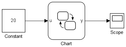
Consider the following simulink model,

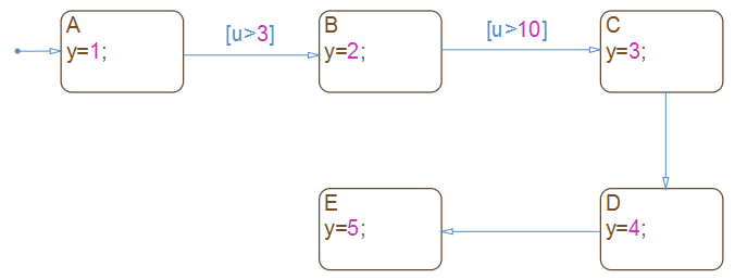
the chart is very simple as shown below.

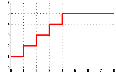
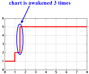
Now, if you run the simulation with a solver w/ variable-step and set the Max step size to be 1,  your chart will be awakened at 0s, 1s, 2s, 3s, 4s, 5s, as is evidence by the chart output y.


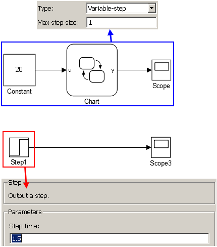
Suppose, you would like to add a source, a step, say, somewhere in the simulink model, and set the step time @1.5s,


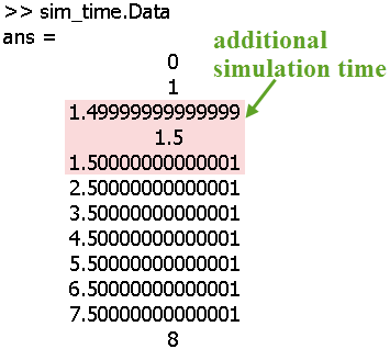
Since 1.5 is not a integer, solver that with variable simulation step will add additional point in its simulation time list (shown below):

As can be seen, when the step block is added into the Simulink model, the solver will simulate at 3 more instants (1.4999,1.5,1.50001), so the stateflow chart will have a totally different response in that case.